MMS (Mobile Mapping System)
In addition to marketing Mobile Mapping Systems (MMS), AISAN TECHNOLOGY strongly supports research and development in automobile-related fields by providing high-accuracy, real time 3D road data. Data of all kinds is enhanced to meet customer needs, so it is applicable to a wide range of fields.
WHAT IS MMS?
“MMS” stands for “Mobile Mapping System," a vehicle-mounted high-accuracy, mobile 3D measurement system developed by Mitsubishi Electric Corporation. Consisting of equipment such as global positioning system (GPS), laser scanners and cameras mounted on a vehicle, the MMS can efficiently acquire precise 3D position data including buildings, road shape, signs/marking, guardrails, characters printed on roads, manholes, and area surrounding the road while driving

MMS Mechanism
1. Vehicle mounted equipment (vehicle type: X320R)
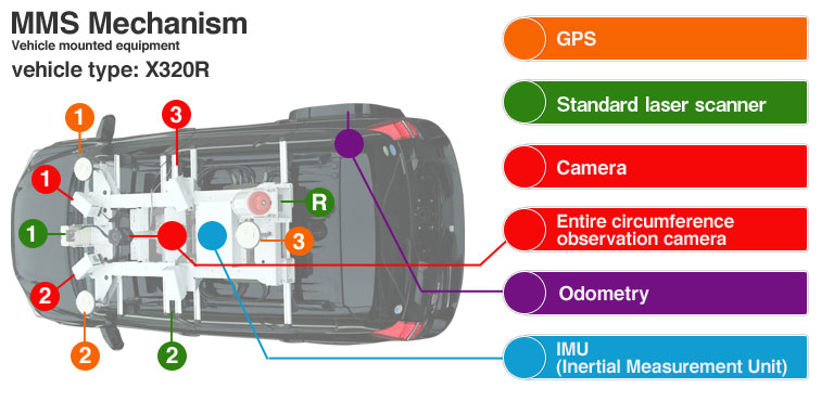
| GPS | Self-positioning accuracy within 0.06 m (rms)
Consists of 3 vehicle-mounted units. * Assumes GPS reception environment is favorable. |
|---|---|
| Standard laser scanner | No. of points per second per unit: 13,757 points/sec (27,100 points/sec for K320)
Viewing angle: 180°, Range: 30 m (65 m for K320) |
| Camera | No. of pixels: 5 million
Viewing angle per unit in horizontal direction: 80° 64° in vertical direction, max. No. of images: 10 images per second |
| Entire circumference observation camera | |
| Odometry | Error of ± 1 m when traveling 1 km continuously without GPS reception
* Provided as reference only; depends on driving conditions. * High-accuracy mapping under bridges is made possible by utilizing land map update function. |
| IMU(Inertial Measurement Unit) | |
| Long distance laser | 300,000 laser points per second at 200 m (max. 50,000 points/sec at 500 m); viewing angle of 360°, range of 500 m |
2. Flow of calculation
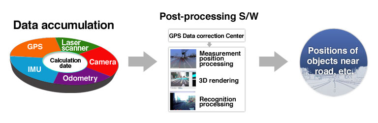
Basic road data
Various types of data obtained while traveling are utilized as basic data to support road and map infrastructure.
Preview when traveling
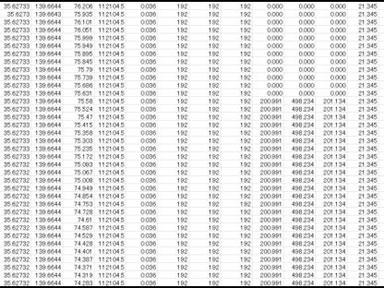
Vehicle self-positioning (X, Y, Z)
Point cloud (color)
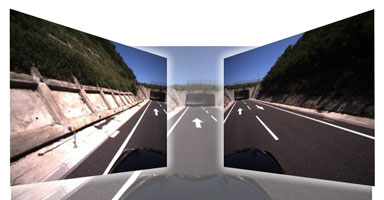
Image data (5 million pixels)
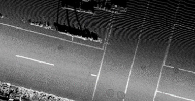
Point cloud (reflective luminance)
On-site work
- Initialization travel: FIX to serve as calculation origin, vehicle azimuth angle detection, IMU offset data log acquisition (approx. 20 min.).
- Calculation: Requires a vehicle driver and an equipment operator (calculation); can be conducted at speeds of 20 to 80 kph.
- Finish travel: FIX at origin point to serve as end of calculation.
* Initialization and finish travel are not absolutely required. (Implemented to enhance accuracy.)
3. Mobile Mapping System (MMS) Features
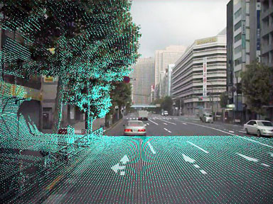
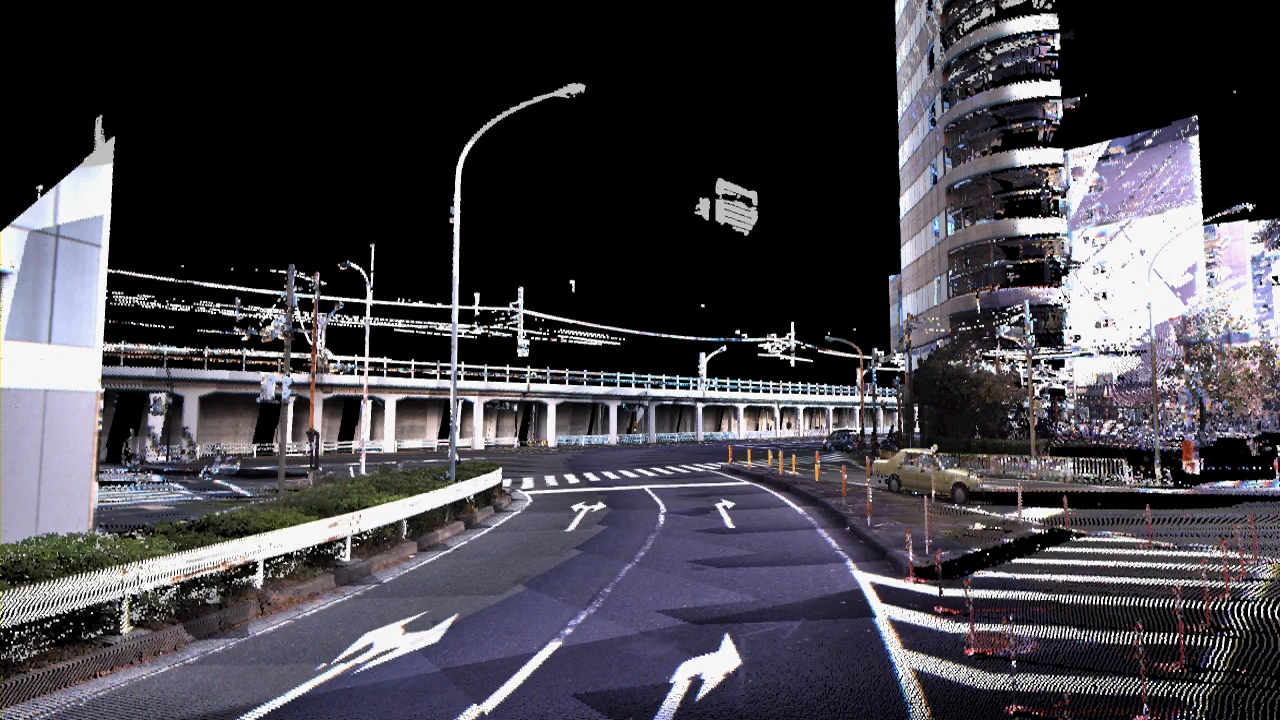
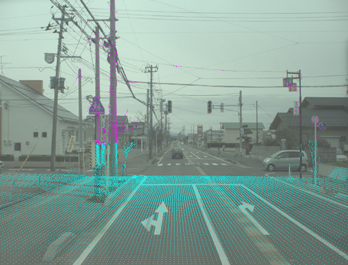
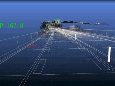
Point cloud/image layering
MMS acquisition point cloud
Each and every individual point in point clouds has high-accuracy positioning data based on vehicle self-positioning. The standard laser point pitch is 8 cm in the transverse direction, and approx. 20 cm in the vertical direction at a speed of 60 kph (15 cm at 60 kph for K320).
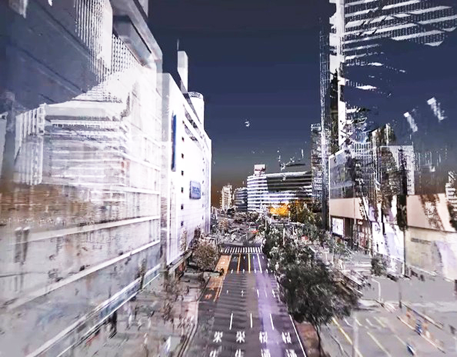
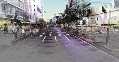
Urban area calculation (Nagoya)
Urban area calculation (Sakuragicho)
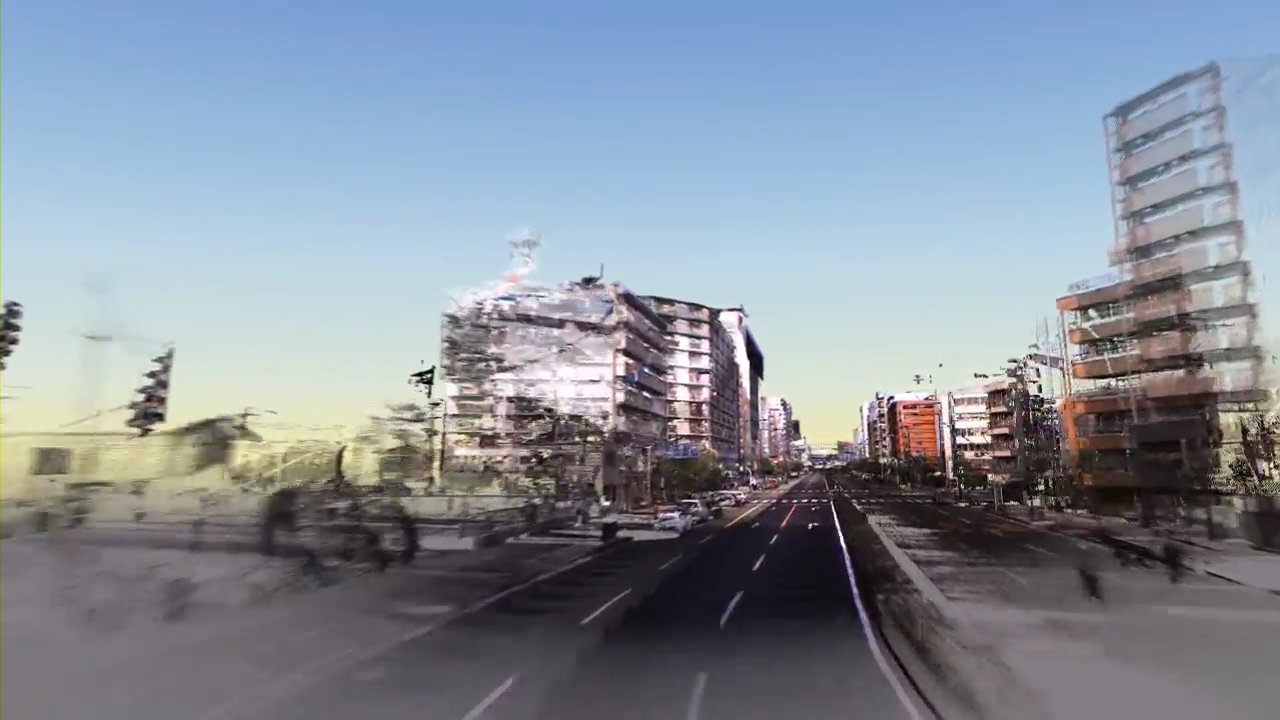
Urban area calculation (Shin-Osaka)
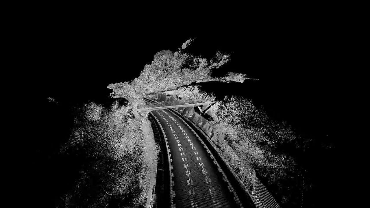
Road calculation (Tomei Expressway)
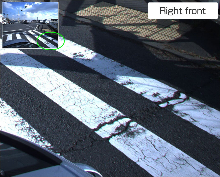
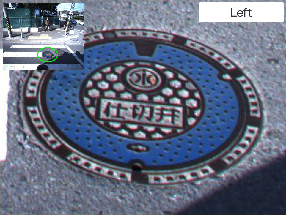
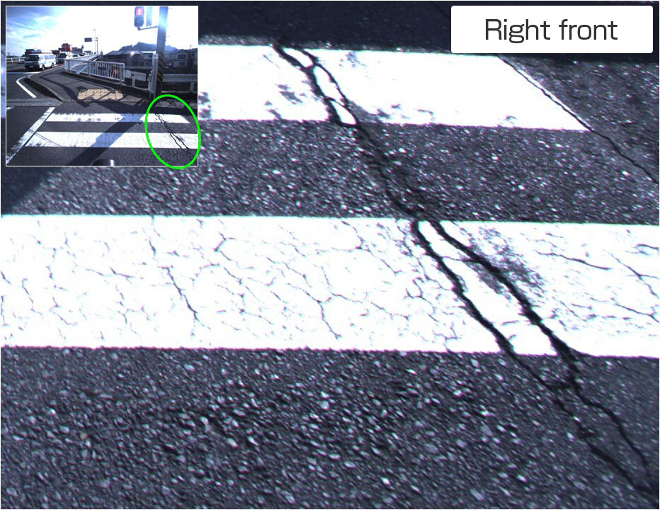
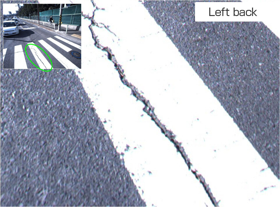
Camera acquired images
Offers entire circumference imaging with a maximum of 6 high-accuracy cameras mounted in front/back and left/right side of vehicle; each camera offers resolution of 5 million pixels, photographing interval of 10 images per second, and distance-specified wide angle (80 degrees in horizontal direction and 64 degrees in vertical direction).

Point cloud/image layering
The angle of the laser scanner and camera is adjusted by rigorous calibration, and calculation is conducted by precisely overlapping laser point clouds with camera images. This enables efficient mapping by compensating for the visual shortcomings of laser point clouds.
High-accuracy measurement
Offers 3-dimensional position measurement within absolute accuracy of 10 cm.
GPS antennas, IMU, cameras and standard lasers are mounted on the roof of the vehicle as a unit. Offers measurement with absolute accuracy of within 10 cm or relative accuracy of within 1 cm within a 7-meter perimeter of road and roadside, even without a ground control point (GCP) in the GPS field of vision. An MMS-X320R equipped with long-range, high-density lasers can measure with absolute accuracy of within 10 cm throughout an 80-meter perimeter.
It also offers measurement at speeds of 20 to 80 kph; data collection accuracy does not diminish even when traveling on an expressway. Laser scanners are capable of acquiring reflective luminance, thus enabling nighttime measurement as well. Also makes point density space transversally to provide a more accurate understanding of transversal road shape. Conforms to “Manual for Numerical Topographical Map Creation Using Vehicle Mounted Mobile Measurement Systems (draft)” of the Geographical Survey Institute. We have experience with Regulation 17 (Toyonaka City, Takatsuki City, Kobe City, Kamigoricho) of Public Survey Standards, and have extensive experience in public surveying.
Enables consecutive mounting of entire circumference observation cameras.
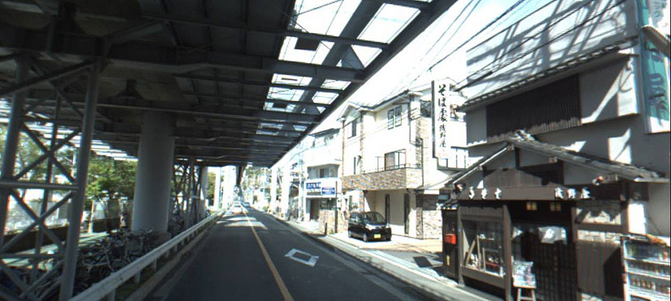
Ladybug entire circumference observation cameras
Equipping a vehicle with Ladybug entire circumference observation cameras enables you to acquire images of the entire periphery. The cameras are perfectly interlocked with existing MMS equipment, and are perfectly synchronized with vehicle self-positioning.
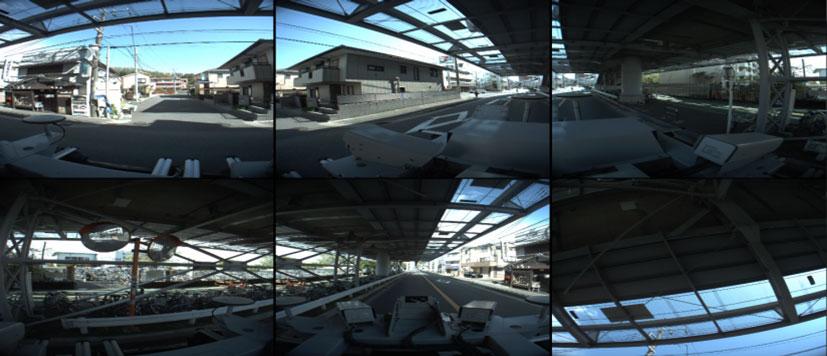
All cameras mode
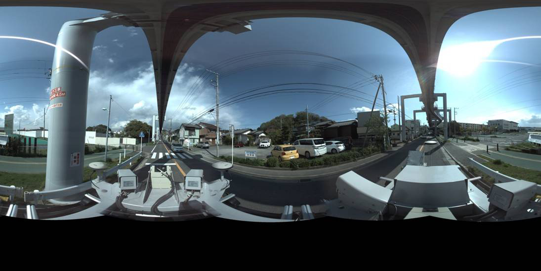
Panorama mode
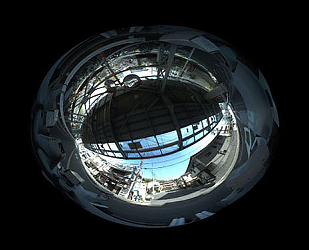
Dome mode
Entire circumference mode
Application Example
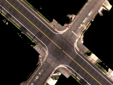
Ortho images
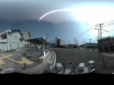
Entire circumference images
3D road maps
Automobile GPS mapping support
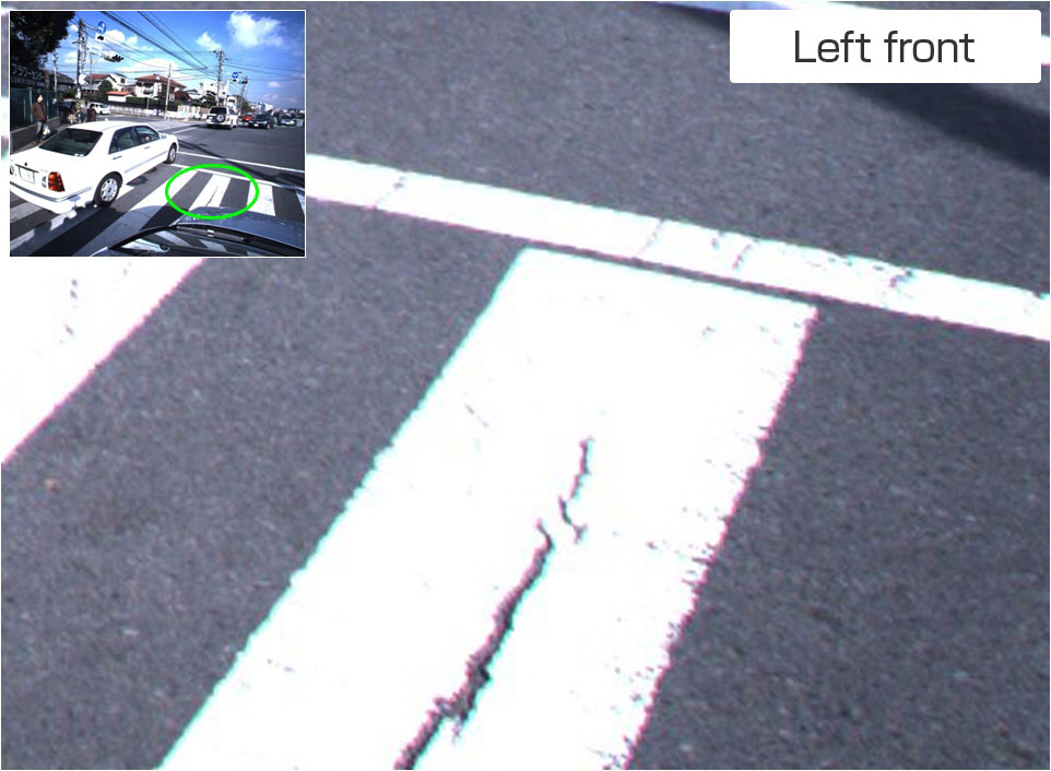
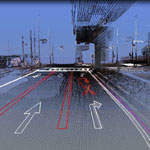
Danger prevention
Simulation
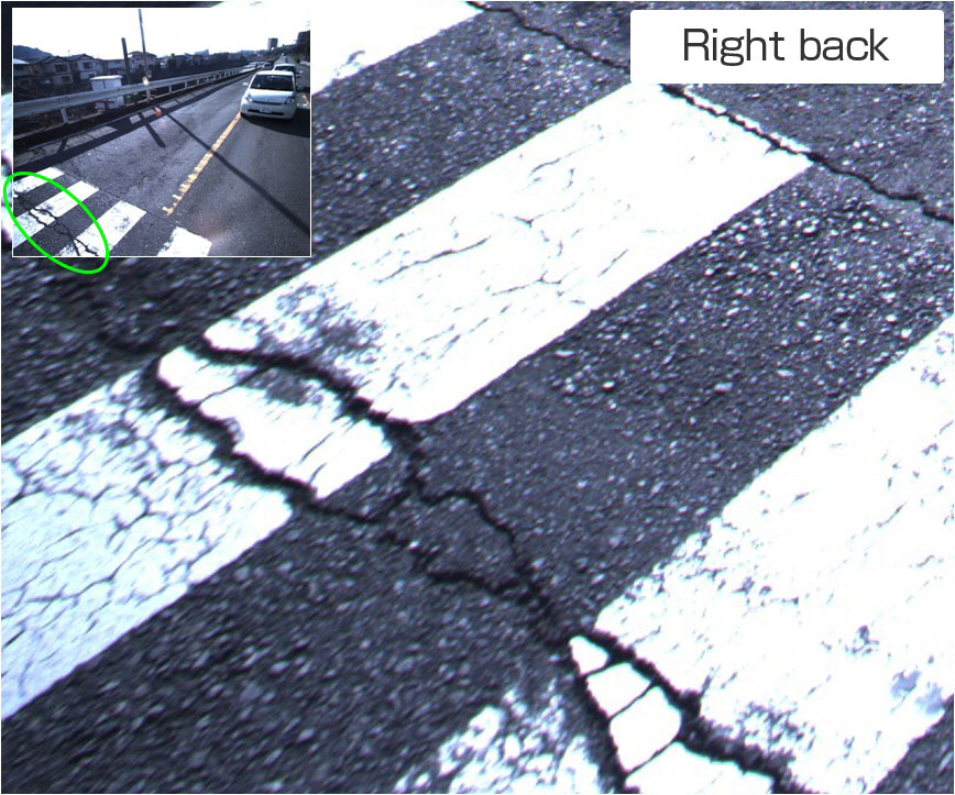
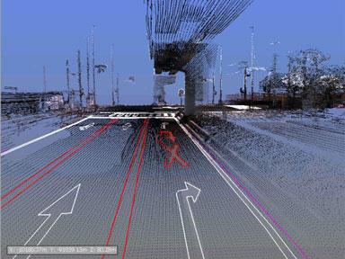
Automatically extracts curbs and traffic instructions painted on the road which are needed for danger prevention such as demarcation lines based on high-accuracy data acquired by MMS. Can also be used for simulation of a vehicle and various components related to suspension, etc., by accurately reproducing road surface data.
Vehicle motion simulation
(Source:Virtual Mechanics Corporation)
Automatic modeling
VR data
Automatic travel/driving support
Converts road element data (curves, gradients, traffic signals, signs, etc.) into text to construct data to support automatic travel/driving. We are also developing high-accuracy VR automatic creation support tools.
Road element data
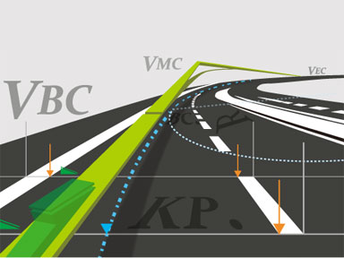
Linear element data
Road element data
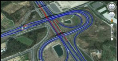
Calculation Examples
Example of Ohashi junction calculation

Mapping of the famous Ohashi junction that runs through Shibuya city of Tokyo by MMS. Mapping took 40 minutes, including 10 minutes in tunnels. The mapping consisted of 45 million calculation points. The data for invisible tunnel areas obtained by drawing long curves was precise, and was furthermore obtained by extremely dense laser data.
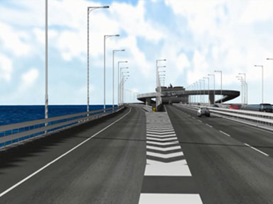
Example of VR data creation using MMS data

We can produce realistic VR data using point cloud data measured by MMS. There are examples of MMS data being used for commercially available VR software and MMS-CG data that can be viewed on Internet Explorer browsers.
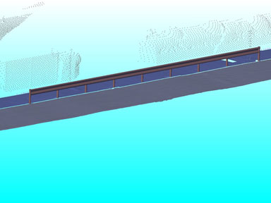
Creation of 3D maps for simulation
Enables highly detailed, high-accuracy 3D reproductions utilizing advanced attitude measurement. Even more realistic expressions can be obtained by reference color processing of images during point cloud processing. Offers efficient creation of high-accuracy 3D data by compounding with ground laser results.
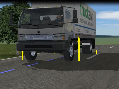
Example of usage for vehicle motion simulation in VR space
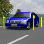
We provide high-accuracy road surface data obtained by MMS measurements for automobile behavior simulation systems. The data is used for simulating vehicle motion in VR spaces. Enables realistic analysis by accurate formation of road surfaces.